How to make Verilog Testbench
April 8, 2021 2021-11-05 17:17How to make Verilog Testbench

How to make Verilog Testbench
TestBench:
In Verilog is a predefined sequence of input combinations to observe the response of DUT (Design under Test). It ensures the intent of the design using different types of input vectors.
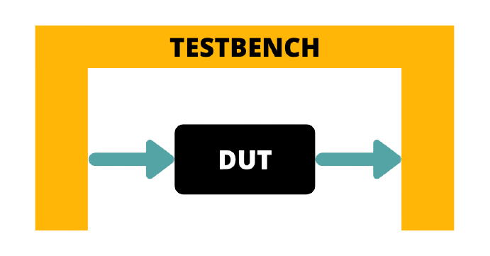
Need of the Testbench:
Most of the beginners observes the response of their designs by forcing the input vectors manually on the waveform window. For a newbie it is all right to start with this method, but, imagine if you are going to make some large designs means you have now more numbers of the inputs and outputs say around more than 10 then designer will not be able to test the design by simple forcing and making changes again and again. this process can take much longer time to close your design.
To make the design time shorter we use some predefined sequence of the inputs which are connected to the DUT now designer have to run this testbench and observe the desired output response. This method allows debugging simpler and efficient.
The DUT can be a behavioral, gate level or dataflow implementation of any design. Verilog test bench is nothing but a Verilog module. It is helpful when we need to use millions of gates on a single chip. It is also helpful while debugging and helps in debugging fast. It can be written before or after the main module but is executed only after the main module is executed. Test Bench gives designer, the liberty to use a number of inputs and observing their corresponding output in the design at the same time. Also this helps in testing the dynamic behavior of the circuit.
Steps to make a Testbench:
STEP 1: To create a dummy template that declares inputs to the DUT as reg and outputs from the DUT as wires. The module name in this template must be different from that of the main module.
reg a1,b1; // outputs from the testbench are reg type
wire s1,c1; // inputs to the testbench are wire type
STEP 2: Connecting the DUT with testbench using Instantiation
Test bench helps in stimulating the DUT by instantiating it in the test bench. Instantiation means nesting of modules. While instantiating, connections to the ports of the module must be specified.
There are two ways to instantiate a module:
- Connection “by position” of the variables.
In the example used above, this type of instantiation is used in this way:
half_adder h1 (a1, b1, s1, c1);
where h1 is the name of instance used for connectivity with the main module and this name can be chosen randomly. Variable a1 is getting connected with the first variable of the design port (i.e. a), the variable b1 is getting connected with the second variable of the design port (i.e. b) and c1 with the c, s1 with s according to the position order.
- Connection “by name” of the variables.
Instantiation using the variables’ names is done in this way:
half_adder h2 (.a(a1), .b(b1), .s(s1), .c(c1));
It can be noted down from here that the names of the variables used for instantiation and the variables used in the main module are different, like .a and (a1), where a is the signal of design and a1 is the part of the current module(testbench). Using this style a is getting connected with a1 using a dot(.) operator which brings signal values from the design using the instance name(h2). Same as a and a1, b and b1, s and s1, c and c1 are getting connected.
Note: It is recommended to use “connection by name” because this style is not depends on the position which can be disturbed while removing or inserting any port in the design.
STEP 3: Stimulation of input vectors to the DUT
Always and initial blocks are two procedural blocks that operate on reg data types in a Verilog simulation. Every initial and always block executes at the same time in every module at the start of simulation.
Initial blocks start their execution sequentially at simulation time 0. The keyword initial is followed by a sequence of statements between the keywords begin and end .The execution starts with the first line between the “begin-end pair”. Each line gets executed from top to bottom until a delay is reached. When a delay is reached, the execution of this block gets interrupted and takes a halt until the delay time has passed and then starts executing again.
The “# 5” implies a time delay or wait time of 5 time steps in simulation.
This line is important in a Verilog simulation, because it tells the simulator to wait for 5 nanoseconds before the next simulation.
STEP 4: Displaying the response of the design
$display ($time , “sum=%b; carry= %b”, s , c);
$display is used to print to a line, or any printable content at the end. Variables can also be displayed, and the format for the variables can be binary using %b, hex using %h, or decimal using %d. Another feature used in $display is $time, which prints the current simulation time.
Example of Half adder and its testbench
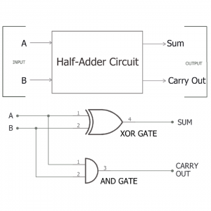
Verilog design of a half adder:
module half_adder(a,b,s,c);

input a,b;  // inputs to the DUT

output s,c;  // outputs  from the DUT

assign {s,c}= a+b+c;

endmodule
Testbench module for the half adder.
module half_adder_tb;  // no port list for the test bench

       reg a1,b1;                           // outputs from the testbench are reg type

       wire s1,c1;                        // inputs to the testbench are wire type

half_adder h1 (a, b, s, c);  // h1 is the variable used for instantiating the main module

always @(s or c or a or b)
begin

 $display ($time , “sum=%b; carry= %b”, s , c); //  prints the binary values of sum and carry

end

Initial
begin

a=0, b=0;
#5 a=0 , b=1;
#5 a=1, b=0;
#5 a=1, b=1;

end
endmodule


endmodule