How UVM RAL Works?
July 7, 2021 2022-01-02 13:06How UVM RAL Works?

How UVM RAL Works?
Today let’s talk about UVM RAL. In this post, I will introduce – What is RAL? and Why RAL is needed? and How the UVM RAL structure looks like?
We know that our DUT (be it an SoC or Subsystem or Design Block) contains a number of different types of registers e.g. control registers, status registers. Most likely these registers are contained within a dedicated block called CSR Block aka “Control and Status Register” Block. But the name could be different in different SoCs. These registers are arranged inside the CSR block based on the address map in the SoC or Subsystem. Both hardware and software need to access control registers to program and control different functionalities in the Chip/Subsystem/Block. Similarly, Status registers are read to know the status of an operation, for example, Interrupt assertion after completion of certain functionality, that means when a certain task is completed by the design, it sets a particular bit/s of the register field to indicate the completion of the operation. e.g. data transfer completion.
To understand RAL, I would recommend you, first and foremost get familiar with the Hardware Registers, if not having already, – I mean, How the registers are defined, what are different types, what are different fields and attributes?
The UVM register layer acts similarly by modeling and abstracting registers of a design. It attempts to mirror the design registers by creating a model in the verification testbench. By applying stimulus to the register model, the actual design registers will exhibit the changes applied by the stimulus.
The benefit of this approach comes from the high level of abstraction provided. The bus protocols for accessing registers can change from design to design, but any stimulus developed for verification of the registers doesn’t have to. This makes it easy to port code from one project to the next if the registers are the same. Taking a look at below provides a better understanding of what a register model implementation might look like with respect to the UVM environment.
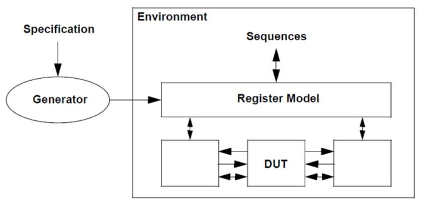
One thing that is interesting about the above figure is the ‘Generator’ bubble. Modern designs have hundreds if not thousands of registers and tens of thousands of register fields. Manually trying to write SystemVerilog code to represent those thousands of registers and register fields would be a gruesome task. This is where generators come into play. A generator’s job is to take the register specifications of a design (usually in the form of a spreadsheet) and automatically ‘generate’ the equivalent register model in SystemVerilog code. In order to use generators or even understand their output, one should first have a good grasp of the UVM register layer.
HOW EXACTLY DOES THE REGISTER LAYER WORK?
First, the register model is built using an organized hierarchical structure. The structure incorporates memory, registers, and address maps into address blocks. Ultimately the blocks communicate with an adapter and receive updates from a predictor, both of which interact with the rest of the verification environment. Once the structure is built, register access API is used to send signals to the DUT where a monitor will report back any information to the register model for the purposes of synchronization.
REGISTER LAYER STRUCTURE
Each register has its own class and each field belonging to the register is created and configured within the class.
class my_register_class extends uvm_reg;

  `uvm_object_utils(my_register_class)   //Register the register with the factory

  rand uvm_reg_field my_register_field;  //Declaring register field

  //Constructor
  //.name         = Name of the register
  //.n_bits       = Number of bits in the register
  //.has_coverage = Coverage of the register
  function new(string name = "my_register_class");
    super.new(.name(name), .n_bits(0), .has_coverage(UVM_NO_COVERAGE));
  endfunction : new

  //Build Function
  virtual function void build();
    //Create the register field and assign the handle to it
    my_register_field = uvm_reg_field::type_id::create("my_register_field");
    my_register_field.configure(.parent                 (this), //parent
                                .size                   (0),    //# bits of the field
                                .lsb_pos                (0),    // LSB position
                                .access                 ("WO"), //Accessibility to write only
                                .volatile               (0),    //Volatility, Can DUT change this value?
                                .reset                  (0),    //Value in reset
                                .has_reset              (1),    // Can the field be reset?
                                .is_rand                (1),    //Can the values be randomized?
                                .individually_accesible (1)     //Does the field occupy by entire byte lane?
    );
  endfunction : build
endclass : my_register_class
Registers are then organized into blocks where a register map is also declared. The register map organizes the registers according to their designated addresses. These blocks are then instantiated in a uvm_environment or the uvm_test depending on preference.
class my_register_block extends uvm_reg_block;

  `uvm_object_utils(my_register_block)   //Register with the factory

  rand my_register_class my_register;  //Register handle
       uvm_reg_map       my_reg_map;   //Register map


  //Constructor
  //.name         = Name of the register
  //.has_coverage = Coverage of the register
  function new(string name = "my_register_block");
    super.new(.name(name), .has_coverage(UVM_NO_COVERAGE));
  endfunction : new

  //Build Function
  virtual function void build();
    my_register = my_register_class::type_id::create("my_register"); //Create the register
    my_register.configure(.blk_parent (this)); //parent block
    my_register.build();                       //Build the register fields

    my_reg_map = create_map(.name      (my_reg_map),         //create register map
                            .base_addr (8'h00),              //offset from the base address
                            .n_byetes  (1),                  //Byte width of the address
                            .endian    (UVM_LITTLE_ENDIAN)); //Endianness

    my_reg_map.add_reg(.rg     (my_register), //register instance
                       .offset (8'h00),       //offset from the base address
                       .rights ("WO"));       //Write Only

    lock_model(); //lock

  endfunction : build

endclass : my_register_class
Up next is the creation of an adapter in the agent. The adapter is what makes abstraction possible. It acts as a bridge between the model and the lower levels. Its function is twofold: it must convert register model transactions to the lower level bus transactions and it must convert any lower-level bus transactions to register model transactions.
class my_register_adapter extends uvm_reg_adapter;

  `uvm_object_utils(my_register_adapter)   //Register with the factory


  //Constructor
  function new(string name = "");
    super.new(name);
  endfunction : new

  //Build Function
  virtual function uvm_sequence_item reg2bus(const ref uvm_reg_bus_op rw);
    my_transaction_class my transaction = my_transaction_class::type_id::create("my_transaction");
    my_transaction.my_register_field = rw.data;
    return my_transaction;
  endfunction : reg2bus

  virtual function void bus2reg(uvm_sequence_item bus_item, ref uvm_reg_bus_op rw);
    my_transaction_class my transaction;

    if(! $cast (my_transaction, bus_item))
    begin
      `uvm_fatal("BUS_ITEM_ERROR", "bus_item cannot be converted to my_transaction")
    end

    rw.kind   = UVM_WRITE;
    rw.data   = my_transaction.my_register_field;
    rw.status = UVM_IS_OK;
    return;

  endfunction : bus2reg

endclass : my_register_adapter
The predictor receives information from the monitor such that changes in values in the registers of the DUT are passed back to the register model.
typedef uvm_reg_predictor#(my_transaction_class) my_reg_predictor;uvm_reg_predictor parameterized with the my_transaction_class
Eventually, the structure that is created looks similar to the diagram, below.
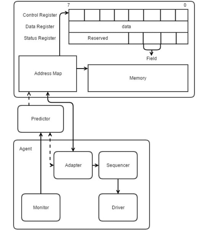
Until now, only registers have been considered, but the register layer also allows memory to be modeled as well. You can see from the image above a memory module is represented in the model, but that discussion is for another time.
Now that the structure has been described; how do we generate stimulus?
Register access is dictated by the register API. Methods, like write() and read() called from a sequence, will send data through the register model to the sequencer, then the driver, and ultimately to the DUT. The monitor picks up any activity and sends it back to the predictor, at which point the predictor will send the data to the adapter where the bus data is converted to a register model format for the register model value to be updated through a predict() method call.
WRITE
virtual task write(
  output uvm_status_e      status,
   input uvm_reg_data_t    value,
   input uvm_path_e        path      = UVM_DEFAULT_PATH,
   input uvm_reg_map       map       = null,
   input uvm_sequence_base parent    = null,
   input int               prior     = -1,
   input uvm_object        extension = null,
   input string            fname     = "",
   input int               lineno    = 0
)
READ
virtual task read(
  output uvm_status_e      status,
  output uvm_reg_data_t    value,
   input uvm_path_e        path      = UVM_DEFAULT_PATH,
   input uvm_reg_map       map       = null,
   input uvm_sequence_base parent    = null,
   input int               prior     = -1,
   input uvm_object        extension = null,
   input string            fname     = "",
   input int               lineno    = 0
)
class my_register_sequence extends uvm_reg_sequence;

  `uvm_object_utils(my_register_sequence)   //Register with the factory

  my_register_block block;

  //Constructor
  function new(string name = "");
    super.new(name);
  endfunction : new

  //Build Function
  virtual task body();
    uvm_status_e status;
    int data = 42;

    block.my_register.write(.status(status), .value(value), .path(UVM_FRONTDOOR). .parent(this));
    block.my_register.read(.status(status), .value(value), .path(UVM_FRONTDOOR). .parent(this));

  endtask : body

endclass : my_register_sequence
A sequence is created to call the API (write() and read()) which will cause movement of data.
Sequences are built to house any register access method calls. The block is declared (notice it does not have to call the create() method) and the registers are referenced hierarchically in the body task to call write() and read(). There also exists peek() and poke() which are utilized for individual field accesses. Many other register access methods exist, including: mirror(), get(), set(), reset(), and more.
Obviously, not everything about the UVM register layer is explicitly talked about here, but I tried to provide an overall idea of what the register layer is and how it’s used so that getting started won’t be so intimidating. There are plenty of examples out there. In order to really get to know the register layer, tons of additional reading, examples browsing, and actual practice have to be done.
I believe, you enjoyed this post! If yes, keep posting your comments, so that I got to know your views. Till next post, stay safe and healthy! Take care, see you again soon with a new post !! Keep on learning, Keep on growing !!